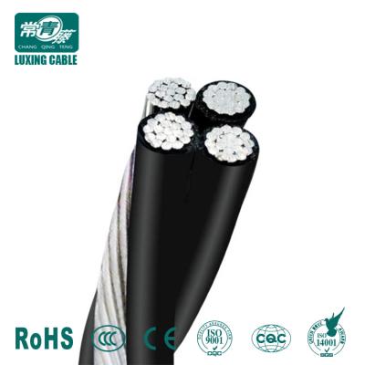

Medium Voltage Cable
MV Cables 1.8/3kV To 26/35kV To IEC60502 XLPE Insulated Non-Armoured Cable
- Main target market:
- Minimum order quantity :
- 100
Exhibit parameters
- Exhibit codeпјҡSN009709
- Size of exhibitsпјҲmmпјүпјҡ25-630 mm2
- Model of exhibitsпјҡ
- Materials of exhibitsпјҡ
- Color of exhibitsпјҡBlack,Orange,Red and so on
- Place of deliveryпјҡChina-SHAN DONG -DE ZHOU
- Raw material production placeпјҡChina-SHAN DONG -DE ZHOU
- Features of exhibitsпјҡ
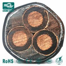
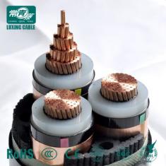
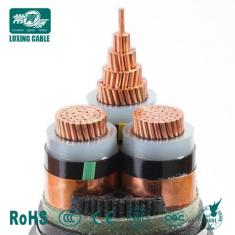
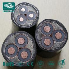
Details of exhibits
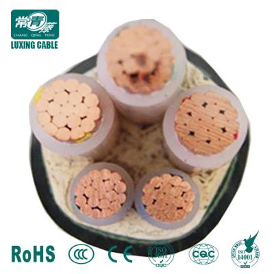
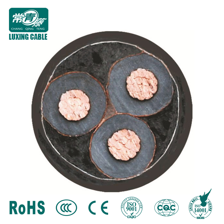
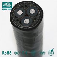
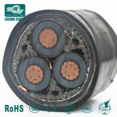
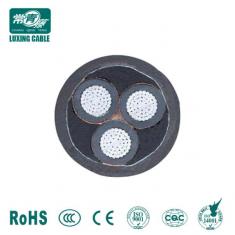
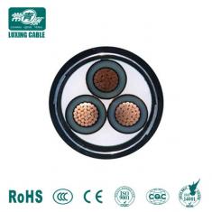
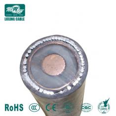
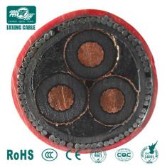
CONSTRUCTION:

1. Stranded compacted copper conductor class 2
2. Extruded semi-conductive conductor screen
3. XLPE insulation
4. Extruded semi-conductive insulation screen
5. Copper tape screen
6. PP Filling
7. Non-woven fabrics wrapping
8. PVC inner sheath
9. Steel wire armored
10. Non-woven fabrics wrapping
11. LSZH(Low Smoke Zero Halogen) outer sheath
APPLICATION
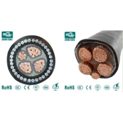
YJV32-Copper Conductor XLPE Insulated Steel Wire Armoured LSZH Sheathed Power&Mains Cable.
Copper XLPE SWA Armoured Cable is suitable for using in power distribution networks or fixed installations for industrial equipments with rated voltage up to and including 1.8/3kV, 3.6/6kV, 6/10kV 8.7/15kV, 12/20kV, 21/35kV, 26/35kV.
CABLE STANDARDS
GB/T12706-2008,IEC,BS,VDE,ASTM and etc. upon request.


BASIC INFORMATION
Code Name
YJV32
Rated Voltage (Uo/U)
1.8/3kV, 3.6/6kV, 6/10kV 8.7/15kV, 12/20kV, 21/35kV, 26/35kV.
Cable Structure
Copper Conductor/XLPE Insulation/Steel Wire Armoured/LSZH Sheath
CONSTRUCTION
Conductor
Number of conductors:1,3
The conductors shall comply with the requirement given in IEC
Insulation
XLPE(Cross-linked Polyethylene) according to IEC
Sheath
PVC(Polyaluminium Chloride) according to IEC
Metal screen
Copper Tape Screen
Armoured Layer
Steel Wire
CHARACTERISTICS
Conductor temperature
Maximum conductor temperature in normal use: 90в„ғ
Max.short-circuit temperature
Maximum shall not exceed 250в„ғ(5s Max,Duration)
Installation temperature
Ambient temperature under installation shall not be below 0в„ғ
Minimum bending radius
The bending radius of cable: (D-Diameter of cable)
For Three Core CableвҖ”вҖ”вҖ”вҖ”вҖ”вҖ”вҖ”вҖ”вҖ”вҖ”вҖ”вҖ”-вүҘ15D
For Single Core CableвҖ”вҖ”вҖ”вҖ”вҖ”вҖ”вҖ”вҖ”вҖ”вҖ”вҖ”вҖ”-вүҘ20D
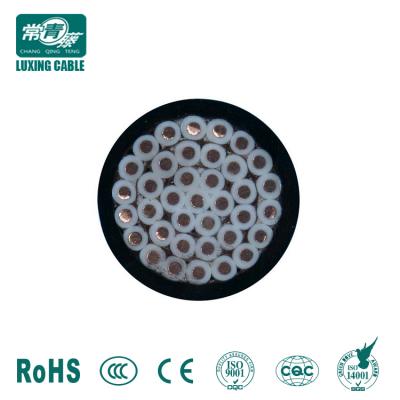
Description:
APPLICATIONS
The three core cables are designed for distribution of electrical power with nominal voltage Uo/U ranging from 3.6/6.6KV to 19/33KV and frequency 50Hz.
They are suitable for installation mostly in power supply stations, indoors and in cable ducts, outdoors, underground and in water as well as for installation on cable trays for industries, switchboards and power stations.
STANDARD
BS 6622
BS 7835 (LSZH Version)
CONSTRUCTION


Conductor | Plain annealed copper or aluminium complying with IEC 60228/BS 6360. Copper conductors shall be stranded (class 2) and aluminium conductors shall be either solid or stranded (class 2). |
Conductor Screen | Extruded layer of semi-conducting cross-linkable compound is applied over the conductor and shall cover the surface completely. The minimum thickness is 0.3mm and the maximum resistivity shall not exceed 500 Ohm-m at 90В°C. |
Insulation | Insulation is of cross-linked polyethylene compound XLPE (GP8) conforming to BS 7655-1.3 or EPR (GP7), conforming to BS 7655-1.2. |
Table 1. Insulation Thickness
Nom. Cross Section Area | Insulation Thickness at Nominal Voltage | ||||
3.8/6.6KV (Um=7.2KV) | 6.35/11KV (Um=12KV) | 8.7/15KV (Um=17.5KV) | 12.7/22KV (Um=24KV) | 19/33KV (Um=36KV) | |
mm^2 | mm | mm | mm | mm | mm |
70 вҖ“ 185 | 2.5 | 3.4 | 4.5 | 5.5 | 8.0 |
240 | 2.6 | 3.4 | 4.5 | 5.5 | 8.0 |
300 | 2.8 | 3.4 | 4.5 | 5.5 | 8.0 |
400 | 3.0 | 3.4 | 4.5 | 5.5 | 8.0 |
Above 500 | 3.2 | 3.4 | 4.5 | 5.5 | 8.0 |
Insulaton Screen | Extruded layer of semi-conducting cross-linkable compound is applied over the insulation. The extruded semi-conducting layer shall consist of bonded or cold strippable semi-conducting compound capable of removal for jointing or terminating. As an option, a semi-conducting tape may be applied over the extruded semi-conducting layer as a bedding for the metallic layer. The minimum thickness is 0.3 mm and the maximum resistivity is 500 Ohm-m at 90В°C. The screen is tightly fitted to the insulation to exclude all air voids and can be easily hand stripped on site. |
Inner Covering & Fillers | For cables with a collective metallic layer or cables with a metallic layer over each individual cores with additional collective metallic layers, semi-conducting inner covering and fillers shall be applied over the laid up cores. The inner covering is made of non hygroscopic material, except if the cable is to be made longitudinally watertight. The inner covering shall be extruded or lapped. |
The approximate thickness of extruded inner coverings is given in Table 2:
Table 2. Approximate Thickness of Extruded Inner Coverings
Ficititous Diameter over Laid Up Cores | Approx. Thickress of Extruded Inner Covering | |
mm | mm | |
> | < | |
35 | 45 | 1.0 |
25 | 35 | 1.2 |
35 | 45 | 1.4 |
45 | 60 | 1.6 |
60 | 80 | 1.8 |
80 | - | 2.0 |
*The approximate thickness of lapped inner coverings shall be 0.6mm.
Metallic Layer | The metallic layer shall be applied over each core or applied as a collective screen. The metallic screen shall consist of either copper tapes or a concentric layer of copper wires or a combination of tapes and wires. The metallic layer provides an earth fault current path, capable of withstanding fault current to earth of 1000A for one second at maximum temperature 160В°C. Copper wires are applied over the conducting water blocking layer with a minimum diameter of 0.5mm. And over the copper wires, copper tape with minimum thickness of 0.1mm can be applied helically with overlap. |
Total cross section of copper wire screen is shown in table 3:
Nominal Cross-Section Area of Cable | Minimum Cross-Section of Copper Wire Screen Area | DC Resistance of the Copper Wire Screen |
mm^2 | mm^2 | mm |
up to 120 | 16 | 1.06 |
150-300 | 25 | 0.72 |
400-630 | 35 | 0.51 |
Table 3. Minimum Total Cross Section of Copper Wire Screen & DC Resistance of The Screen
Separation Sheath (for armoured cable) | The separation sheath comprises a layer of extruded PVC, PE or LSZH. The nominal thickness is calculated by 0.02Du + 0.6mm where Du is the fictitious diameter under the sheath in mm. The nominal separation sheath thickness shall not be less than 1.2mm. |
Armour (for armoured cable) | The armour consists of galvanized steel wire applied over the inner covering with diameter specified as in Table 4. |
Table 4. Armour Wire Diameter
Fictitiious Diameter under the Armour | Armour Wire Diameter | |
mm | mm | |
> | < | |
25 | 1.6 | |
25 | 35 | 2.0 |
35 | 60 | 2.5 |
60 | - | 3.15 |
Over Sheath | Overall sheath comprises a layer of extruded either PVC type 9 conforming to BS 7665-4.2 or MDPE type TS2 conforming to BS 7655-10.1; LSZH can be offered as an option. The over sheath is normally black in colour. When a DC voltage test is to be performed on the over sheath, a semi-conducting layer such as graphite coating shall be applied over the surface of the extruded over sheath. The nominal over sheath thickness is calculated by 0.035+D where D is the diameter immediately under the over sheath in mm. For cables with the over sheath not applied over the armour, the nominal over sheath thickness shall not be less than 1.4mm. And for cables with over sheath applied over the armour, the nominal over sheath thickness shall not be less than 1.8mm. |
PHYSICAL PROPERTIES
Operating Temperature | up to 90В°C |
Temperature Range | -5В°C ( PVC or LSZH sheath ); -20В°C ( PE sheath ) |
Short Circuit Temperature | 250В°C (short circuit duration up to 5 seconds) |
Bending Radius | 15 x OD |
Table 5. Nominal /Operating /Test Voltages
Rated Voltage Uo/U | Operating Voltage (Um) | Testing Voltage (rms) |
3.8/6.6KV | 7.2KV | 15KV |
6.35/11KV | 12KV | 25.5KV |
8.7/15KV |
More exhibits
Waiting to accept invitation...
Invite you to a video call
Copyright В© 2006-2022 еңЁзәҝеңәжҷҜпјҲеҢ—дә¬пјү科жҠҖжңүйҷҗе…¬еҸё. All Rights ReservedPrivacy Policy дә¬ICPеӨҮ20020516еҸ·-3 дә¬е…¬зҪ‘е®үеӨҮ 11010502042835еҸ· дә¬е…¬зҪ‘е®үеӨҮ 11010502042835еҸ·
|